
|
CASPOC Schematic
Components
Input voltage Vin = 380V
Expected output voltage Vout = 48V
Two Mosfet switched by at 50% duty cycle.
in this topology we have a transformer which we can use to stepup or step down the voltage. we also introduice isolation by
having different grounds from the between the primary and the secondary windings. as we can see the forward converter has the
topology of a Buck converter.
Diode D4 and D3 are used to prevent the transformer from saturation
Questions and remarks
It is assumed :
forward Converter operates in the steady state
forward Converter operates in continuous conduction mode
Mosfet voltage rating will be 380V as compared to using a single switchj forward converter
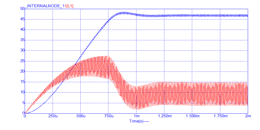
SCOPE 1:
Dark blue gragh ---> represents the Voltage output
Red gragh ---> current measurement across the Inductor
both the ripple voltage and current through the inductor are less than 1V
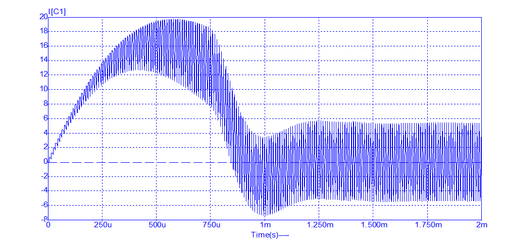
SCOPE 2:
Represents the current across the capacitor
We notice that the Iac current goes through the Capacitor.
 |
 |