


HystereseCurrentControl - Three Phase Hysteresis Current Controller
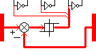
Connection Diagram:
| G1H | G1L | G2H | G2L | G3H | G3L | ||
| ISOLL1 |
| IIST1 | |||||
| ISOLL2 | IIST2 | ||||||
| ISOLL3 | IIST3 | ||||||
| Connections(12) | Position | Remark |
| ISOLL3 | Left | Reference Current L3 |
| ISOLL2 | Left | Reference Current L2 |
| ISOLL1 | Left | Reference Current L1 |
| IIST3 | Right | Measured Current L3 |
| IIST2 | Right | Measured Current L2 |
| IIST1 | Right | Measured Current L1 |
| G3L | Top | Gate Low Switch Leg 3 |
| G3H | Top | Gate High Switch Leg 3 |
| G2L | Top | Gate Low Switch Leg 2 |
| G2H | Top | Gate High Switch Leg 2 |
| G1L | Top | Gate Low Switch Leg 1 |
| G1H | Top | Gate High Switch Leg 1 |
| Parameters(2) | Default | Remark |
| HysteresisBand | 100m | Hysteresis Band in Ampere. If Iin-Iref>HysteresisBand the output becomes positive at the first clock signal |
| Fs | 10kHz | Switching Frequency |
| Function | This controller compares the reference currents with the measured currents. If ( Reference Current - Measured Current > HysteresisBand) the output is high. The gate signals are synchronized to the switching frequency. |
|
| Status | Standard | |
| Export of Embedded C Code | YES | |
| Select from | Components\Library\Control\FieldOrientedControl | |
See also
CurrentControl, DirectVectorControl, DirectVectorControlParameters, HystereseCurrentControlSinglePhase, IdIqWslip, K_Tau, PMSMRotorFluxObserver, PWM_CONVERTER, PWM_CONVERTER_Fs_A, VCO, w2a, w2a_AdvanceAngle,