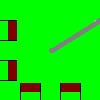
Unipolar - Unipolar Stepper Motor

Connection Diagram:
| M | |||||
| A1 | 
| ROTOR | |||
| A2 | |||||
| A3 | |||||
| A4 | |||||
| B1 | B2 | B3 | B4 | ||
| Connections(10) | Position | Remark |
| ROTOR | Right | |
| M | Top | |
| B4 | Bottom | |
| B3 | Bottom | |
| B2 | Bottom | |
| B1 | Bottom | |
| A4 | Left | |
| A3 | Left | |
| A2 | Left | |
| A1 | Left |
| Parameters(7) | Default | Remark |
| p | 2 | |
| JR | 10u | |
| LS | 50m | |
| RS | 100 | |
| f | 1m | |
| Ke | 50m | |
| DetentTorque[Nm] | 10m |
| Function | The Unipolar Stepper Motor has four stator windings. | |
| Note | The inductance and resistance are given per phase. | |
| Status | Standard | |
| Select from | Components\Library\ElectricalMachines\Stepper | |
See also
Bipolar,


