


InverterIGBTaveraged - Inverter IGBT Thermal System
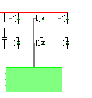
Connection Diagram:
| DC |
| ||||||||||||
| U | |||||||||||||
| V | |||||||||||||
| W | |||||||||||||
| GND | |||||||||||||
| ZA | |||||||||||||
| ZB | |||||||||||||
| ZC | |||||||||||||
| Connections(30) | Position | Remark |
| ZC | Left | |
| ZB | Left | |
| ZA | Left | |
| W | Right | |
| V | Right | |
| U | Right | |
| GND | Left | |
| DC | Left |
| Parameters(7) | Default | Remark |
| Resr[Ohm] | 10m | Equivalent series resistance of the DC link capacitor [Ohm] |
| Cdc[F] | 100uF | Capacitance of the DC link capacitor [Farad] |
| InitialCdcVoltage[V] | 600 | Initial voltage of the DC link capacitor [V] |
| Vce[V] | 1 | IGBT on Vce |
| Rce[Ohm] | 25m | IGBT on resistance |
| Vd[V] | 0.5 | Diode on Vd |
| Rd[Ohm] | 10m | Diode on resistance |
| Function | IGBT inverter system model with loss calculation. The IGBT switches are replaced by an averaged model. Therefore the simulation speed is large compared to the model with the IGBT switches | |
| Note | This model can not be used to regenerate energy from the three pahse terminals via the diodes to the DC link, since the diodes are not present in the model. | |
| Status | Standard | |
| Select from | Components\Library\PowerConverters\Inverters3phase | |
See also
BlankingTime, BrushlessGatePWM, BrushlessHall2SixPulse, BrushlessPosition2SixPulse, Inverter, InverterDQ, Inverter_Averaged, Inverter_IGBT, Inverter_IGBT_Level1, INVERTER_MOSFET, pwm3, PWM_Converter6, PWM_ConverterSymCarrier, PWM_symmetrical, SixPulseAngleControlled, SixPulseAngleControlled120Degr, SixPulseFrequencyControlled, SixStep, SoftStartControl, Softstarter, SVM, VF, VSI_GTO, VSI_PWM,