


MCT - MCT
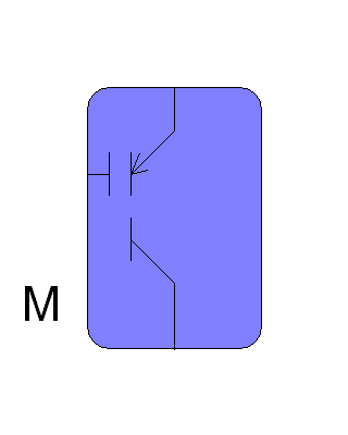
Connection Diagram:
| A | ||
| G |
| |
| M | ||
| K |
| Connections(17) | Position | Remark |
| M | Left | Connect to a .Model database |
| K | Bottom | Cathode |
| G | Left | Gate of the MCT |
| A | Top | Anode |
| Parameters(10) | Default | Remark |
| Ron | 10m | On state MCT resistance |
| Roff | 1e9 | Off state MCT resistance |
| Von | 0.6 | On state MCTvoltage |
| RG | 10 | MCT internal gate resistance |
| CGA | 1nF | MCT Gate Anode capacitance |
| ReverseBreakDownVoltage[V] | 25 | Reverse Break Down voltage of the MCT[V] |
| RonBreakDown | 100m | On state resistance during break down |
| ReverseBreakDownCurrent[V] | 1 | BreakDown current at the break down voltage [A] |
| VonGateTreshold[V] | -5 | Treshold gate turn on voltage |
| VoffGateTreshold[V] | 5 | Treshold gate turn off voltage |
| Function | Ideal MCT model with MOS gate and gate delay | |
| Special | The Gate is a circuit node. The delay time due to charging CGA is modeled, | |
| Status | Standard | |
| Select from | Components\Library\Semiconductor\MCT | |
See also