


LinearPMSM - Linear Permanent Magnet Synchronous Machine
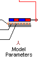
Connection Diagram:
| TEL | ||
| R |
| SHAFT |
| S | ||
| T | ||
| M |
| Connections(6) | Position | Remark |
| TEL | Top | |
| T | Left | |
| SHAFT | Right | |
| S | Left | |
| R | Left | |
| M | Bottom |
| Parameters(6) | Default | Remark |
| Mass[Kg] | 100m | Mass of the rotor in [Kg] |
| LS[H] | 15m | Winding inductance per phase in [H] |
| RS[ohm] | 10m | Winding resistance per phase [ohm] |
| Friction[Nm/Rad/s] | 1m | Bearing friction in [Nm/Rad/s] |
| Ke[Vpeak/Rad/s]=[Nm/A] | 1 | Torque constant in [Nm/A] or back EMF constant in [Vpeak/Rad/s] |
| PolePair[.] | 1 | Number of pole pairs [#] |
| Function | Linear Permanent Magnet Synchronous Machine with sinusoidal back emf | |
| Note | The inductance and resistance are given per phase. The resistance and inductance between two terminals equals 2*Rs and 2*Ls | |
| Status | Standard | |
| Select from | Components\Library\ElectricalMachines\PMSM | |
See also
BLACM, IPM, LdLq, LdLqFile, LdLqKT, PMSM, PMSM9phase, PMSMq, PMSM_DQ, PMSM_DQdq,